I am creating a replica of the DEC PDP-8/e architecture in an FPGA from schematics of the original hardware. So how did I end up with a project like this?
The story begins with me wanting to have a computer with one of those front panels that have many, many lights where you can really see, in real time, what the computer is doing while it is executing code. Not because I am nostalgic for a prior experience with any of those — I was born a bit too late for that and my first computer as a kid was a Commodore 64.
Now, the front panel era ended around 40 years ago with the advent of microprocessors and computers of that age and older that are complete and working are hard to find and not cheap. And even if you do, there’s the issue of weight, size (complete systems with peripherals fill at least a rack) and power consumption. So what to do — build myself a small one with modern technology of course.
While there’s many computer architectures of that era to choose from, the various PDP machines by DEC are significant and well known (and documented) due to their large numbers. The most important are probably the 12 bit PDP-8, the 16 bit PDP-11 and the 36 bit PDP-10. While the PDP-11 is enticing because of the possibility to run UNIX I wanted to start with something simpler, so I chose the PDP-8.
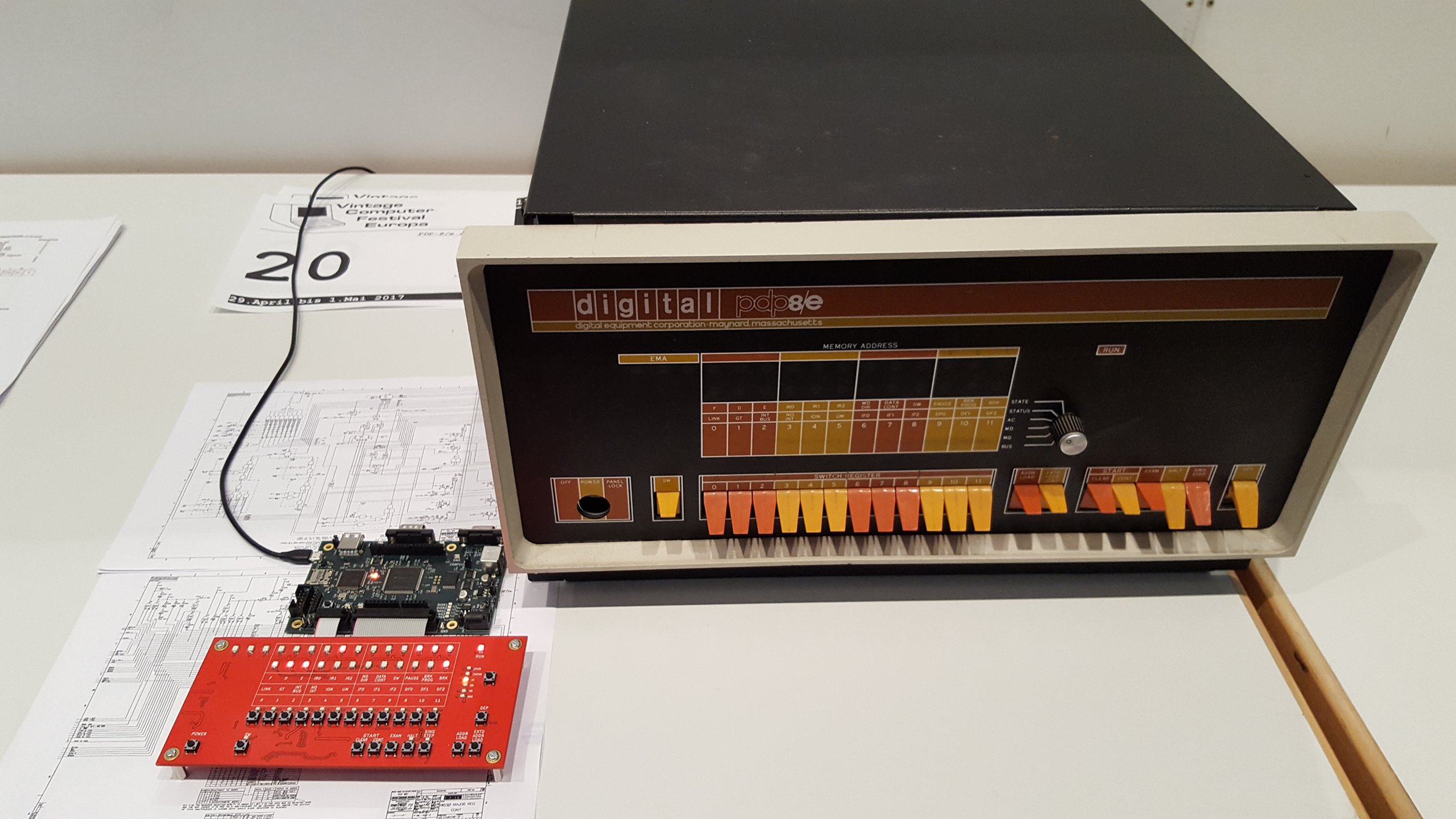
My implementation on display next to a real PDP-8/e at VCFe 18.0
The Original
DEC started the PDP-8 line of computers programmed data processors designed
as low cost machines in 1965. It is a quite minimalist 12 bit architecture based
on the earlier PDP-5, and by minimalist I mean seriously minimal. If you are
familiar with early 8 bit microprocessors like the 6502 or 8080 you will find
them luxuriously equipped in comparison.
The PDP-8 base architecture has a program counter (PC) and an accumulator (AC)1. That’s it. There are no pointer or index registers2. There is no stack. It has addition and AND instructions but subtractions and OR operations have to be manually coded. The optional Extended Arithmetic Element adds the MQ register but that’s really it for visible registers. The Wikipedia page on the PDP-8 has a good detailed description.
Regarding technology, the PDP-8 series has been in production long enough to get the whole range of implementations from discrete transistor logic to microprocessors. The 8/e which I target was right in the middle, implemented in TTL logic where each IC contains multiple logic elements. This allowed the CPU itself (including timing generator) to fit on three large circuit boards plugged into a backplane. Complete systems would have at least another board for the front panel and multiple boards for the core memory, then additional boards for whatever options and peripherals were desired.
Design Choices and Comparisons
I’m not the only one who had the idea to build something like that, of course. Among the other modern PDP-8 implementations with a front panel, probably the most prominent project is the Spare Time Gizmos SBC6120 which is a PDP-8 single board computer built around the Harris/Intersil HD-6120 microprocessor, which implementes the PDP-8 architecture, combined with a nice front panel. Another is the PiDP-8/I, which is another nice front panel (modeled after the 8/i which has even more lights) driven by the simh simulator running under Linux on a Raspberry Pi.
My goal is to get front panel lights that appear exactly like the real ones in operation. This necessitates driving the lights at full speed as they change with every instruction or even within instructions for some display selections. For example, if you run a tight loop that does nothing but increment AC while displaying that register, it would appear that all lights are lit at equal but less than full brightness. The reason is that the loop runs at such a high speed that even the most significant bit, which is blinking the slowest, is too fast to see flicker. Hence they are all effectively 50% on, just at different frequencies, and appear to be constantly light at the same brightness.
This is where the other projects lack what I am looking for. The PiDP-8/I is a multiplexed display which updates at something like 30 Hz or 60 Hz, taking whatever value is current in the simulation software at the time. All the states the lights took inbetween are lost and consequently there is flickering where there shouldn’t be. On the SBC6120 at least the address lines appear to update at full speed as these are the actual RAM address lines. However the used 6120 microprocessor does not have required data for the indicator display externally available. Instead, the SBC6120 runs an interrupt at 30 Hz to trap into its firmware/monitor program which then reads the current state and writes it to the front panel display, which is essentially just another peripheral. A different considerable problem with the SBC6120 is its use of the 6100 microprocessor family ICs, which are themselves long out of production and not trivial (or cheaply) to come by.
Given that the way to go is to drive all lights in step with every cycle3, this can be done by a software running on a dedicated microcontroller — which is how I started — or by implementing a real CPU with all the needed outputs in an FPGA — which is the project I am writing about.
In the next post I give an overview of the hardware I built so far and some of the features that are yet to be implemented.
-
With an associated link bit which is a little different from a carry bit in that it is treated as a thirteenth bit, i.e. it will be flipped rather than set when a carry occurs. ↩︎
-
Although there are 8 specially treated memory addresses that will pre-increment when used in indirect addressing. ↩︎
-
Basic cycles on the PDP-8/e are 1.4 µs for memory modifying cycles and fast cycles of 1.2 µs for everything else. Instructions can be one to three cycles long. ↩︎